2007 Yamaha Grizzly 700 Throttle Body Removal Diagram
The “2007 Yamaha Grizzly 700 Throttle Body Removal Diagram” is an informative visual representation that outlines the step-by-step process of detaching and disconnecting the throttle body, a device controlling the flow of fuel to the engine, from the 2007 Yamaha Grizzly 700 ATV. This comprehensive illustration, depicted as a precise line drawing, offers enthusiasts and mechanics a clear and concise guide to effectively separate the throttle body, ensuring accurate disassembly and reassembly through a detailed and easy-to-follow drawing.
Removing The Throttle Body Diagram
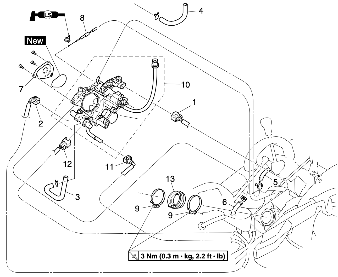
To perform the removal, simply follow the steps provided below in numerical order. Make sure to carefully reverse the removal procedure in the exact opposite order as listed for a seamless installation process.
- Intake Air Pressure Sensor Coupler: The intake air pressure sensor coupler is a connector that links the intake air pressure sensor to the engine control unit. This sensor measures the air pressure within the intake manifold, providing essential data for the engine control unit to determine the appropriate fuel injection and ignition timing.
- Throttle Position Sensor Coupler: The throttle position sensor coupler is a connector that links the throttle position sensor to the engine control unit. This sensor monitors the position of the throttle plate, informing the engine control unit about the driver’s throttle input. This data is used to adjust the air-fuel mixture and optimize engine performance.
- Breather Hose (Air Filter Case to Throttle Body): The breather hose connects the air filter case to the throttle body. It allows fresh, filtered air to enter the throttle body, contributing to the combustion process and preventing contaminants from entering the engine.
- Breather Hose (Air Filter Case to Fast Idle Plunger Unit): Similar to the previous breather hose, this component connects the air filter case to the fast idle plunger unit. It facilitates the passage of filtered air, contributing to efficient engine combustion and preventing impurities from infiltrating the system.
- Fast Idle Plunger Outlet Hose: This hose connects to the outlet of the fast idle plunger unit, allowing excess air to be released as needed during cold starts. The fast idle plunger helps maintain a stable idle speed when the engine is cold.
- Fast Idle Plunger Inlet Hose: The fast idle plunger inlet hose connects to the inlet of the fast idle plunger unit. It supplies the plunger unit with air, which aids in adjusting the engine’s idle speed during cold starts.
- Throttle Cable Housing Cover: The throttle cable housing cover provides protection and support for the throttle cable, which controls the opening and closing of the throttle plate. It ensures smooth and precise throttle control.
- Throttle Cable: The throttle cable is a crucial link between the driver’s accelerator pedal input and the throttle plate. It regulates the amount of air entering the engine, which in turn affects the engine’s power output.
- Throttle Body Joint Clamp Screw: This screw secures the throttle body joint in place, ensuring a tight connection between the throttle body and other components of the intake system.
- Throttle Body Assembly: The throttle body assembly regulates the airflow into the engine. It houses the throttle plate, which can be adjusted by the throttle cable and the driver’s input, controlling the engine’s power and speed.
- Fuel Hose: The fuel hose transports fuel from the fuel tank to the fuel injector. It plays a critical role in delivering the precise amount of fuel required for combustion.
- Fuel Injector Coupler: The fuel injector coupler is a connector that links the fuel injector to the engine control unit. Fuel injectors spray fuel directly into the combustion chamber based on signals from the control unit, ensuring efficient and controlled fuel delivery.
- Throttle Body Joint: The throttle body joint connects the throttle body to the intake manifold. It forms a crucial seal to prevent air leaks, ensuring accurate airflow control.
The throttle system is a complex arrangement of components working together to regulate the air and fuel mixture entering a combustion engine. Each part, from sensors to hoses to the throttle body itself, plays a vital role in ensuring optimal engine performance, efficiency, and responsiveness. Understanding these components helps us appreciate the intricacies of internal combustion engines and their role in powering various vehicles and machines.
Referencces:
2007 Yamaha Grizzly 700 Model YFM7FGPW Factory Service Manual. Chapter 6.33-6.34, Pages 305-306.