2007 Yamaha Grizzly 700 Front Brake Pads Diagram
The title “2007 Yamaha Grizzly 700 Front Brake Pads Diagram” refers to a visual representation, often presented as a simplified drawing or illustration, which elucidates the arrangement and components of the braking system’s front brake pads on the 2007 Yamaha Grizzly 700 ATV. This diagram provides a schematic representation, offering insight into the positioning of the thin blocks that grip the rotating brake disc, constituting a fundamental device for lowering a moving vehicle’s speed. By visually depicting the intricate layout of these front brake pads, the diagram serves as an informative guide for ATV enthusiasts and mechanics alike, enhancing understanding of the vital braking mechanisms located at the front of the vehicle.
Front Brake Pad Diagram
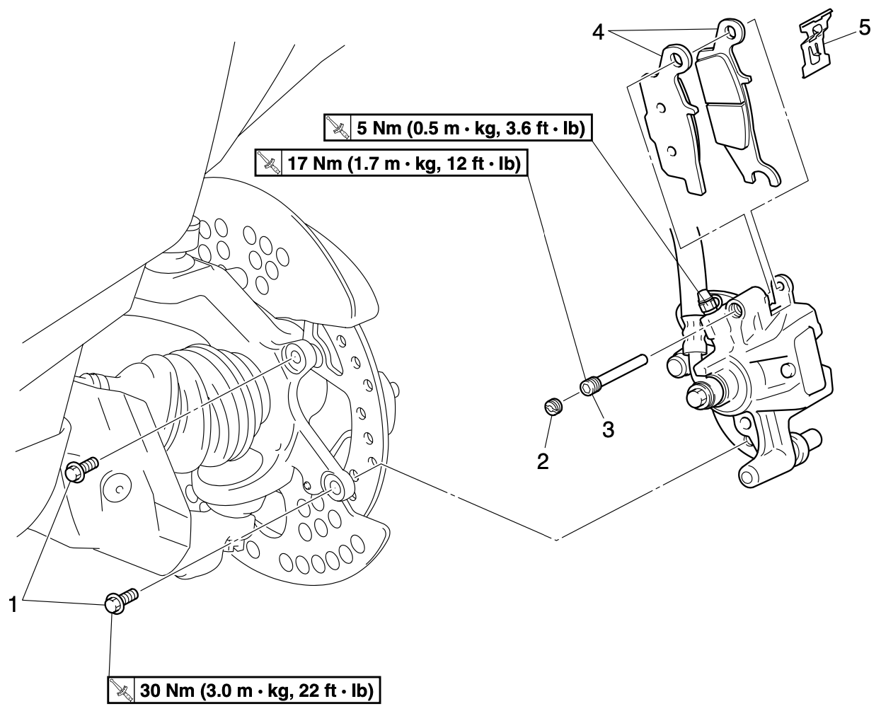
1. Front Brake Caliper Bolt:
The front brake caliper bolt serves as a vital connection point between the brake caliper and the ATV’s suspension. This bolt securely fastens the caliper to the mounting bracket, allowing the caliper to effectively clamp down on the brake rotor when the brakes are engaged. Torque specifications for the caliper bolt are outlined by the manufacturer to ensure proper fastening and prevent any unintended loosening during operation.
2. Brake Pad Holding Bolt Plug:
The brake pad holding bolt plug is a protective covering that secures the brake pad holding bolt in place. This plug not only prevents environmental debris from compromising the integrity of the bolt but also maintains the brake pad’s stability. The plug’s torque specifications are provided by the manufacturer to guarantee the proper retention of the holding bolt and the brake pad it secures.
3. Brake Pad Holding Bolt:
The brake pad holding bolt is a critical fastening component that secures the brake pad to the caliper’s mounting bracket. As the brake caliper squeezes the brake pad against the rotor, it is the holding bolt’s responsibility to maintain the necessary pressure, ensuring effective braking performance. Following the manufacturer’s torque recommendations for this bolt is crucial to prevent over-tightening or under-tightening, which could impact the brake system’s efficiency.
4. Front Brake Pad:
The front brake pad is a friction material that directly interfaces with the brake rotor when the brakes are applied. As the brake caliper clamps down on the rotor, the brake pad generates friction, converting kinetic energy into heat and bringing the ATV to a controlled stop. The composition and design of the brake pad contribute to its efficiency, and adhering to manufacturer-recommended torque specifications guarantees proper installation and operation.
5. Brake Pad Spring:
The brake pad spring is a specialized component designed to ensure consistent contact between the brake pad and the rotor. It exerts pressure on the brake pad, maintaining proper positioning within the caliper and facilitating even wear over time. Following the manufacturer’s torque guidelines when installing the brake pad spring helps maintain its optimal functionality, contributing to the brake system’s reliability.
When conducting the disassembly of the front brake system for the 2007 Yamaha Grizzly 700 ATV, it is essential to adhere to the specified sequence for component removal. Start by carefully detaching the Front Brake Caliper Bolt, which holds the caliper securely in place on the mounting bracket. Following this, proceed to remove the Brake Pad Holding Bolt Plug, ensuring the protective covering is gently extracted without causing damage. Subsequently, take out the Brake Pad Holding Bolt itself, which releases the brake pad from its position within the caliper’s mounting bracket. With the bolt removed, you can then gently slide out the Front Brake Pad. Lastly, conclude the disassembly by removing the Brake Pad Spring, a component designed to maintain consistent pressure on the brake pad for effective contact with the rotor. Adhering to this specified order of removal will facilitate a smooth and organized disassembly process. For installation, reverse the removal procedure.
Reference:
2007 Yamaha Grizzly 700 Model YFM7FGPW Factory Service Manual. Chapter 8-1, Page 348.